
|
|
Tutorial
We would like to congratulate you for buying CimaGraphi Product.
The CimaGraphi is in fact a package containing four modules.
In this tutorial we will introduce the basic tools of those programs.
We will start with the Trace:
| TRACE, GRAPHICAD, P2P , MILL, RESULTS, HOMEPAGE. |
 |
General
CimaGraphi’s main purpose is to design and manufacture part with an artistic flavor. The design modules include Trace (Raster to vector conversion and graphic editing), GraphiCad (Drafting and text handling) and Picture To Part (P2P – 3D surface design and editing)). The manufacturing module is the Mill (CAM module). The following tutorial takes you through a step by step journey through Cimagraphi’s design tools leading up to the actual production of a part.
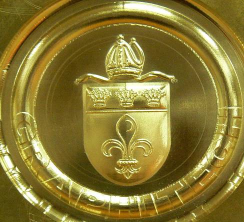
Start image -> end result
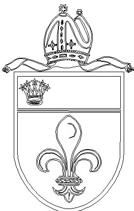
1. We will now begin by pasting the outline,
press on Paste 2. Click on Edit  ,
click on Mark all ,
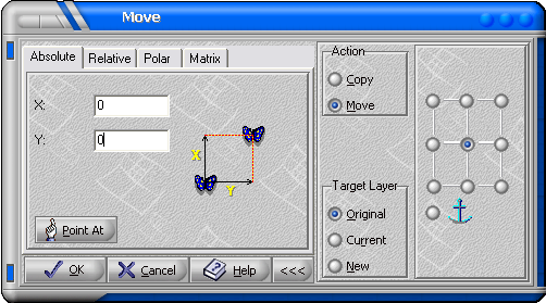
click on Mark all  3. Now we are going to Center the outline to (0, 0). Click on Transform  ,
Click on Move ,
Click on Move In the Move window on Action mark Move, the X: 0, the y: 0. Another Important issue is the Anchor Sign  The
Mark of an anchor means The
Mark of an anchor meansThe relative position we wants in this example we want the center to be at (0, 0).  ,
the
whole outline jumped to (0, 0) ,
the
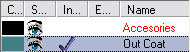
whole outline jumped to (0, 0)4. Now we are going to create layers. Select the "Out Coat" chain and Drag in to the Group Manager. (The Group Manager is located at the bottom left of the screen).  Tip: Use the It will be easier to mark other chains
if you don't see the
created layer 5. Because Using different layers are important let's Practice it. We will do the same that you have done: Follow the table and drag the Chains as a different layers as followed by the Example under. Because Using different layers are important let's Practice it. We will do the same that you have done: Follow the table and drag the Chains as a different layers as followed by the Example under. 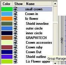 In the end you'll see
all the layers
at the Group Manager the same as in the table
(The exact colors aren't needed), you can Click on Show all Layers  and
You'll see every chain
in a different
layer color. and
You'll see every chain
in a different
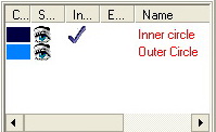
layer color. 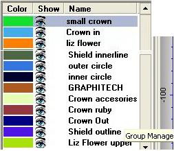 6. Now to see how simple it is, we will make an addition to the outline we made. We will make a new layer for The circle, we will call the new layer In Circle. tip: to do so, fist, create a new layer by clicking on  in
the window we will call the name
as Inner
Circle, Click Ok , now the new layer will appear at the layer list
as in
the window we will call the name
as Inner
Circle, Click Ok , now the new layer will appear at the layer list
as  , it means that the new geometry
will be made
at the marked layer. , it means that the new geometry
will be made
at the marked layer.Let's Make a Circle by using the Circle by Center and Radius  The Radius should be 100 and the X: 0 and
y: 0.
The Radius should be 100 and the X: 0 and
y: 0.7. Create a new Layer called Outer Circle; create a bigger circle with radius 125 in Position X: 0, Y: 0. This is the result: 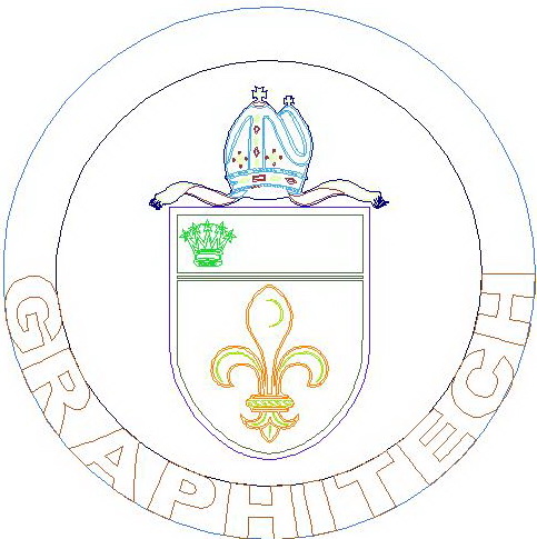 Now we are going to Add Text to the circles. 8. Go to Text Mode by Clicking on  9. Create a New Layer, name it GraphiTech. 10. In Text Mode, click on font  and
Change the font to Arial Black
Bold and click on and
Change the font to Arial Black
Bold and click on  . .11. Double Click in an empty space on the screen to Write without problems. 12. Write 'GRAPHITECH', all in Capital Letters. 13. Mark the Graphitech Layer and Select, from the Text Menu, Text Along the Curve  . .14. Insert the Text by Two Curves  , proportional to the
curves by selecting the point in the curve , proportional to the
curves by selecting the point in the curve  Now the program will require four relative points : The First two points: The
first click on the left side of the out circle, as
close to Y: 0 as possible The second click on the Right side of the out circle, as close to Y: 0 as possible The Seconds two points:The
first click on the left side of the in circle, as
close to Y: 0 as possible The second click on the Right side of the in circle, as close to Y: 0 as possible
  18. Click on Edit  and on Mark all and on Mark all 19. Click on Copy  .
Once again this makes the entire
design
available in all of Cimagraphi’s modules. .
Once again this makes the entire
design
available in all of Cimagraphi’s modules. |
1. Click on Paste 2. In the P2P markings have a different meaning, the layer panel have five Columns: Color, Show  ,
Include, and Exclude. ,
Include, and Exclude.
3. Create a New Component by click on Component  and
on
New Component and
on
New Component  Tip: The Components list can be see it at the bottom of the screen, You can create a new component by clicking right to the component Available on the bottom on the screen.  Like in this example you can see that we can give a name to our components, To do so just right click on the component and click on Name. 4. Select the Text layer and Drag them to text Component on the Bottom right Side. (You can't drag layers except to components under the project itself) Now let's move our layers to the components. Here is a table of the components I made with those layers as followed:
Now We are going to start embossing the components. 5. We will start on the circle component 6. Mark the Inner Circle and the Outer Circle layers 7. Click at the Emboss Icon  ,
now you can check that the Layers
that you want ,
now you can check that the Layers
that you want To emboss are the correct ones at the Mark Box, Then click next 
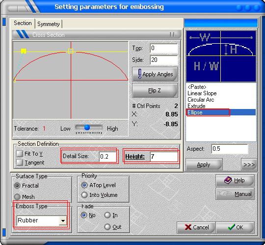
Select: Ellipse; Detail Size: 0.2; Height: 7; Emboss Type ; Rubber, 
Tip: Do not forget to Unmark
after embossing a layer and before Marking 9. Continue with the embossing according to the following table by components:
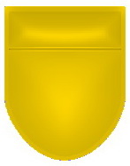
Component Circle:
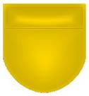
Component shield:
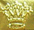
Component small crown:
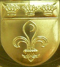
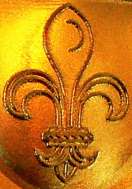
Component Liz flower:
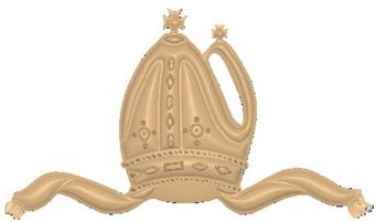
Component crown:
Component text:
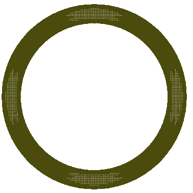
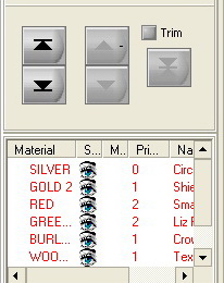
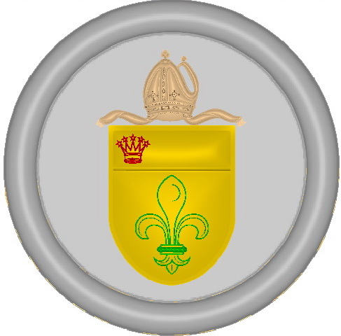
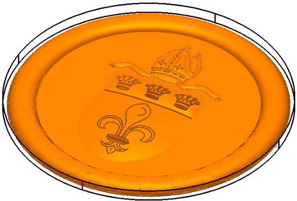
All the components together, we will do so in the Assembly. The question, "why we made several components and not only one or two" surely came up. The reason we made several components is to give more depth to the part we are creating. If we had only one or two parts then the embossing wouldn’t be accurate as we would like it to be, and in the assembly we have more options we can use. We can add components and adjust the components together. What's left now is to assemble the components together. In the P2P on the upper left we have the assemble icon. 10. Click on  Now we can see on the bottom left all our components, We can also choose different material for each component that will reflect the different components with different colors. To choose a material for a component we just need to click on the material and to choose which one we desire. If we want to put a component above another component, its priority should be at a higher level. See on the example that the lower priority is the circle. Above it is the shield. Another important issue is the material for color, Different colors or materials can prepare your work to be as close as you want To create it by a machine or as your final product.
 Until you'll receive the following:
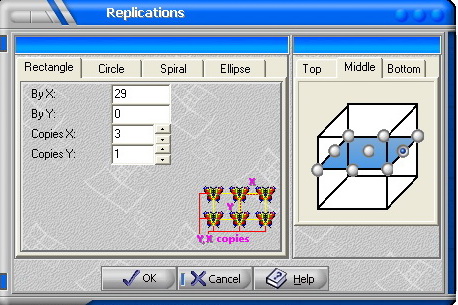
 a window will appear: These are the correct settings it will create another 2 small crowns identical to the one we left. Here is the example:
12. Export to Mill clicking on  13. When "Do you want to weld all the components together" prompted, click No, There is no advantage in welding and it takes a long time. 14. Click on  then then   15. Save the Changes … (Coat of Arms.p2p)   16. Open Mill 
|
| 1. Import the Surface from P2P    2. The Billet Setup opens automatically 3. Select the correct Billet  and
then click on and
then click on  and and 
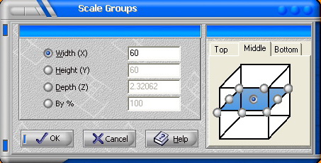
For Scaling let's click on the scale button  and
the dialog box will appear: and
the dialog box will appear:
5. Now we need to adjust the billet to our scaled surface. Let's press on the billet Button  we
just need to click on we
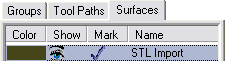
just need to click on  and and  6. Now we can start making our tool path's, in this part I've made 5 different tool path, we will do here only 2 of them, just to get the idea. What we are going to do is to select a Tool to use choose the method we want it to operate. 1st Tool path: 6.1. Click on  6.2. Let us Mark the Group Layer "Outer circle", and the surface we imported From the P2P. tip: In this case, we will select the Surfaces that we have export from P2P and Mark it.  6.4. We need to select a tool  in
this example the tool is: in
this example the tool is: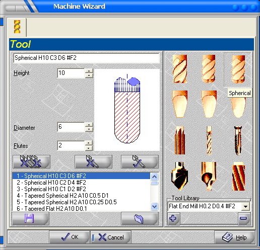
Spherical
tool, Height 2, diameter 6, Flutes 2.Click on
 6.5. Now we need to Select Technology  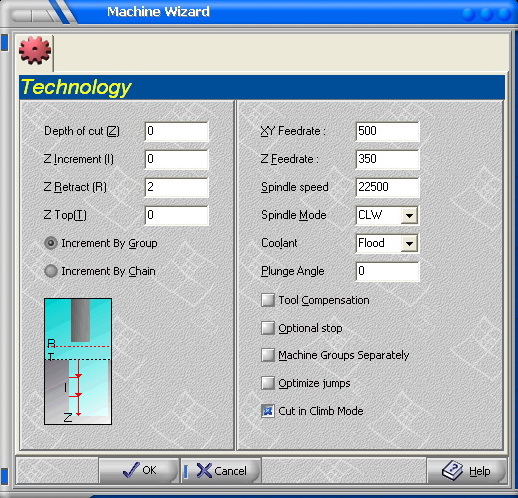
And click
on
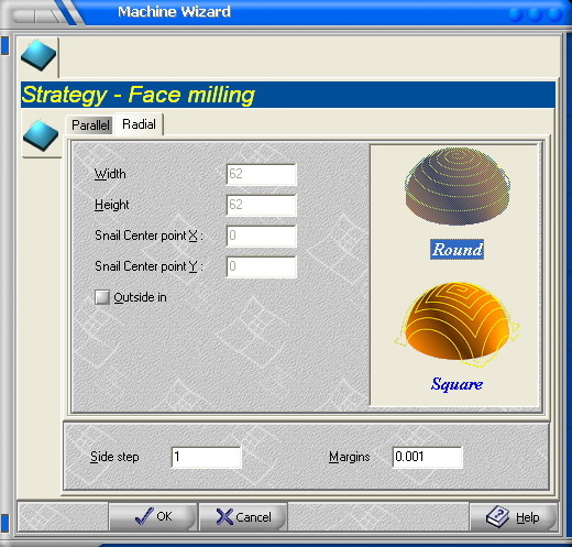
 . .6.6. Select Strategy - Face Milling 
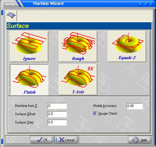
6.7. Select Surface  (Finish) (Finish)
 to
calculate the Tool Path to
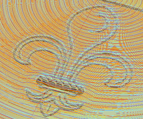
calculate the Tool PathAt the designs screen you'll see the Tool Path 7. Output to Machine, Click on  7.1 Select Tool Path
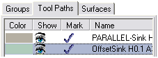 7.2. Click
on
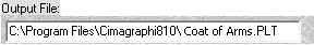
7.3 Give a name to the output file and a correct path
 |
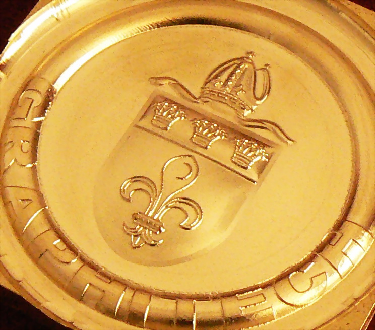
After 6:55 hours this is the result we
received: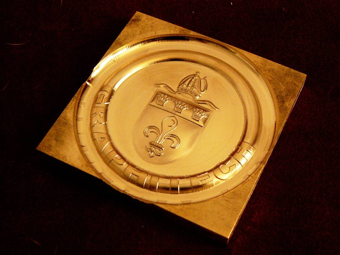
Component shield:
Component small crown:
Component Liz flower:
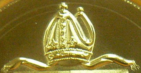
Component crown:
Component text:
|
| Back to GraphiTech Home Page. |


 and in the Dialog box on OK
 (Click
on the icon to Show/Unshow the picture).
(Click
on the icon to Show/Unshow the picture).
 (Select the Chain that you want to
edit).
(Select the Chain that you want to
edit).


 Brake the Chain between the selected
points,
Brake the Chain between the selected
points,


 . Or make sure no chain is selected
(Press the ESC key)
. Or make sure no chain is selected
(Press the ESC key) to transfer the outlines from the
Trace. At this point the outline shape can be pasted into any of the
to transfer the outlines from the
Trace. At this point the outline shape can be pasted into any of the
 to
Show/Unshow the Layer, when it's
open, you
can see the layer, to close, click on it, it will appear
to
Show/Unshow the Layer, when it's
open, you
can see the layer, to close, click on it, it will appear ,
,